Abstract:
This paper introduces how to analyze the curve of the testing result, dig out the reasons of exceeding, and come up with effective solutions so that the equipment can meet EMC standard limit requirement if they exceed the EMC limits.
Key Words:
Exceed EMC standard limit, EMC enhancement
Example 1: Radar Equipment
Nowadays the digital circuits are very intensive and their function is complicated, as a result the electromagnetic interference is inevitable, meanwhile the digit circuits are affected by interference from other components too. So it is necessary to consider EMC at the very beginning of product design so that effective measures could be taken to eliminate interference signals. Take the EMI problems that may exist for the design of certain radar equipment as an example.
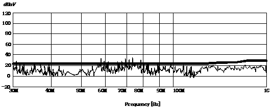
Preliminary testing result according to GJB-151A RE102 of the equipment is shown as figure1, we can see interference at 30MHz and most frequency points between 30MHz and 90MHz exceeds the limit. In order to find out the reasons of exceeding we use a spectrum analyzer to identify the leakage position.
Since the structure and circuit of the equipment is fixed and cannot be changed, we can only improve on the basis of the original.
As we all know the structure of the chassis has a great deal with radiated interference. The components, integrated blocks, wiring of the printed circuit boards inside the cabinet and where there is signal currents may radiate electromagnetic energy. The higher the frequency it is most likely to generates interference signals. If the cabinet is unshielded, the electromagnetic energy will affect the outside devices. If it is metal cabinet or the inner surface of the non-metal cabinet is metal-plated, the electromagnetic energy could be restricted only inside the cabinet.
Fighre1 Testing result according to GJB-151A RE102 of certain radar equipment before enhancement
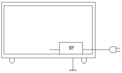
Figure2 Picture of certain radar equipment
1. To improve the cabinet
In order to judge if the radiated interference is mainly caused by chassis leakage, we disconnect the cable and control lines, only leave power lines for which interference control measures already taken to keep the equipment being able to work, then we test the radiated interference again, still interference at most frequency points go beyond the limits, this means there is obvious leakage from chassis or power lines. In order to further identify if it is power line interference or cabinet leakage or both. We moved a near field magnetic field probe( connected with spectrum analyzer) along the chassis slit or holes to fix the leakage point and observe the leakage situation at different frequencies. We found comparatively high field strength at the slit near power supply, and we pasted one conductive metal belt which was well connected with the chassis metal surface to assure good conductivity, then there was obvious decrease of the radiated field strength. The result shows there is leakage from the chassis.
Measures taken could be adding conductive strap to make the chassis slit meeting the requirement, or adopting wave-guide design or reducing the interval space of the stud used to assembly the chassis( along the slit). Once the chassis is well shielded, connect the shielded cable and control lines, retest RE102, we can see there is obvious improvement, shown as Figure3, but still some points go beyond the limit.

Figure3 Testing result after cabinet improvement measures taken
2. Adding EMI filters
Because the electromagnetic interference of the shielded unit coupling to the wires connecting I/O interference and power lines generates interference current and transferred to the outside of the shielded unit, causing transferred interference and radiated interference to outside devices. It is the same that outside EMI interference could enter into the unit through wires connecting I/O interference and power lines and cause radiated interference to the inner equipment of the unit.
Low-pass filters can effectively suppress and prevent interference and reduce the electric level of conducted interference.
For power line, its interference frequency are far higher than its working frequency, as a result low pass filters could well eliminate the interference frequency while let working frequency pass without any attenuation.
For I/O interface wire, its interference frequency are also higher than its working frequency, so low pass filters could well eliminate the interference frequency while let working frequency pass without any attenuation.
But since the working frequency of I/O interface wire is much higher than that of the power line, the insertion loss characteristics of filters matched with them respectively are different, so are the magnetic materials adopted. The former is ferro-nickel and the latter is mn-zn
2.1 How to improve the cable and control lines
a) Replace the current used connector with filtering connector.
b) Reset the input and output lines of EMI filter to prevent coupling between them, so as to secure the filtering effect.
c) Increase grounding points of shielding layer of cable.
d) Insert all the pins of connector to the ground potential to prevent antenna effect.
2.2 How to improve the power lines
For shielded metal cabinet, we should choose filters with separate metal cover and mounted at the input of the power line. And make sure the filter metal cover keeps good electric contact with the cabinet. The ground wire of filter should be fixed with the common grounding metal part at the cabinet or cable output. Shown as figure4.

Figure 4 Right way of EMI filter grounding
After taking the EMC enhancement measures above, the testing result is perfect, see figure5.
Figure 5 Testing result after EMC measures taken
To sum up, the aforementioned measures are all good for EMC improvement, but the most commonly used is to change ground wire structure and cables are enhanced respectively because it is not only cost saving but also the most effective. Though shielding will increase the cost but its shielding effect is preeminent above all other method. So in practice we should mainly consider changing ground wire structure, enhancing cables respectively and improving shielding, also other measures as support.
Example 2: Digital circuit oscillator
Crystal oscillator is absolutely essential for digit circuit design. Oscillator provides reference signal for digit circuit, the higher its oscillation frequency, the richer harmonics generated, in other words, the more serious the interference. For most digit circuits, cover of the oscillator isn’t grounded, nor the PCB board providing efficient grounding area.
More and more electric engineers notice that cover of the oscillator grounded could effectively reduce interference, so keep a grounding area correspond to oscillator and remove the solder mask when wiring the PCB, and solder the cover of oscillator there.
Digital circuit can work according to certain timing sequence only when oscillation level meet the amplitude requirement. However, frequency multiplier harmonics generated by oscillator bring interference, and even disturb the sensitive circuit.
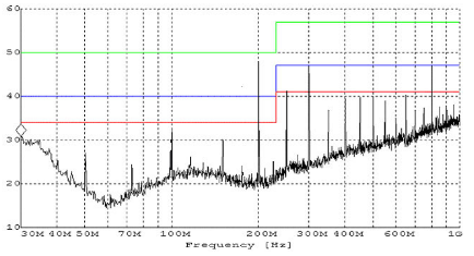
Figure6 shows the frequency multiplier interference amplitude of 25MHz oscillator, we can see there is high spike at 2, 3, 4, 5, 6...times frequency multiplier, it is typical frequency spectrum gram for 25MHz. This gram indicates that the oscillator circuit or ground wire is not properly handled and we must reduce oscillator harmonics radiation.
1. Oscillator grounding
Make sure the grounding area large enough when deal with the grounding issue. If it still exceeds the limit after grounding, but only the amplitude value decreases, then we should also reduce oscillator harmonics radiation.
2. Suppress the amplitude value

Figure6 Typical frequency spectrum gram before EMC enhancement
a) Add attenuators while keeping the sensitivity and noise-signal ratio unchanged. For example, oscillators for VCD, DVD make the equipment hard to meet EMC requirement, reducing oscillator frequency is a feasible solution to solve the problem, but not a sole method.
We can also suppress the amplitude value of multiple oscillator frequencies.
b) To observe if the oscillator waveform is sine wave using a high frequency oscilloscope, if not, change the line-ground capacitor of oscillator to adjust.
c) Add a series of ferrite beads with low reactance and high impedance to the pin connecting oscillator and decoder. The impedance of the ferrite beads is above 50MHz and the higher the better while keeping the reactance not increasing too much.
d) Check if the loop area of power supply of decoder, decoder oscillator clock, high speed signal and the wiring around oscillator is too large, if yes, try to minimize the area.
e) If you already take some of the measures above and the rest are hard to implement, the only thing we can do is to add ferrite core or ferrite beads to the output lines, but this is only a matter of expediency. Shown as figure7:
Figure8: Frequency spectrum gram after EMC enhancement
- ·The Analysis and Solution of EMC Problem for Automatic Control System in Wind Tunnel Laboratory
- ·EMC Enhancement of Radar Equipment
- ·Power Supply of Military Desktop Computer( according to GJB151A Standard)
- ·DCS Automatic Control System and The Electromagnetic Compatibility(EMC) of Inverter
- ·Electromagnetic Compatibility of Central Control System in Coal Washery