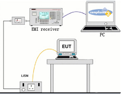
Conducting emission exceeding test is to test whether the equipment under test (EUT) passes the limit of electromagnetic disturbance under the standard frequency band according to the relevant national / industry regulations. Conducting emission test, also known as disturbance voltage test, involves all products as long as they have power lines, including many DC power supply products. In addition, there are also requirement regarding the signal / control lines conducting emission in many standards, usually expressed by the limit of disturbance voltage or disturbance current (There exist some relationships of conversion between them). The insertion loss test (expressed directly by dB) in lamps and lanterns also falls into the category of conduction test.
1. Test Standard
| Category | National Standard | IEC Standard |
| Household appliances, electric tools and other similar appliances | GB4343.1 | CISPR14-1 |
| Information technology equipment | GB9254 | CISPR22 |
| Sound, television, broadcasting receivers and related equipment | GB13837 | CISPR13 |
| Electrical lighting and similar equipment | GB17743 | CISPR15 |
| Industrial, scientific and medical (ISM) RF equipment | GB4824 | CISPR11 |
2. Test Diagram


Conducting Emission Test Diagram
3. Conducting Emission Test Method
1) Instruments and equipment used for conducting emission test: Receiver, LISN (line impedance stabilization network, or AMN artificial power network), Analog Hand, Passive Voltage Probe, Current Probe (CDN used in conjunction with current probe, capacitive voltage probe), DIA (Intermittent interference analyzer used for testing intermittent interference in CISPR14-1), a whole set of equipment for measuring insertion loss and so on. Of course, the PC is also needed. DIA should comply with the requirements of CISPR16-1-1, and other auxiliary devices should comply with the requirements of CISPR16-1-2.
2) Conducting emission test arrangement: there are two types, test on the table or on the floor. Desktop equipment is 80 cm away from LISN, 40cm off the ground flat (here the ground plate can be horizontally connected floor, or the vertical earthing wall of the shielded room). The distance from the ground equipment to the ground plate is allowed to vary according to different standards.
3) Frequency band of conducting emission test: mostly 150kHz-30MHz, but CISPR15 is an exception, for which the disturbance voltage is 9kHz-30MHz and insertion loss 150kHz-1605kHz.
4) Conducting emission test limits: it varies with different standards and different product categories (Group 1 / 2, Class A / R B).
5) Conducting emission test process:
a) AC / DC power disturbance voltage: connect the power plug to the LISN, the receiver RF input is connected to the RF output of the LISN (RF attenuator or pulse limiter is inserted between LISN and receive according to the test requirement), and the L/ N switch of the LISN is switched to select the common mode disturbance voltage to the ground of the test power line.
b) Intermittent interference: this is required by CISPR14-1 and some standards which quotes CISPR14-1, and usually tested using intermittent interference analyzers in conjunction with LISN. The standard also allows for using a combination of oscilloscopes and receivers. The oscilloscope observes the disturbance duration and the receiver observes the disturbance level amplitude.
c) The load disturbance voltage: this is required in CISPR14-1 / CISPR15 and CISPR11. The passive voltage probe is used to strip off the load line insulation which needs to be tested, and the disturbance voltage of the load line terminal to the ground is measured directly by the probe connecting receiver. Note that if the rated current of the device is too large and there is no suitable LISN available, the voltage probe can also be used directly to measure the disturbance voltage at the power supply end.
d) The communication line disturbance voltage / current: is mentioned in CISPR22 There are different testing methods for different types of communication lines. There is detailed description in Annex C, and the advantages and disadvantages of different method are analyzed in Annex F. It mainly depends on the different combination of current probe and CDN, 150Ω earth resistance, capacitive voltage probe to test different types of communication cable, the premise of which is that the ground impedance of the cable under test is 150ohm. The results can be expressed directly by the disturbance current dBuA, or by the disturbance voltage dBuV. The conversion impedance is 150ohms, that means the difference between the two values is 44 dB.
e) Insertion loss: mentioned in CISPR15. Using a receiver to measure the comparative voltage to obtain the value of insertion loss after the signal generated by RF sine wave generator passing through balanced/unbalanced converter, analog modulation and LISN
4. Conclusion of results of the conducted emission test:
Compare the measured values (QP/AV) of receiver geophone with the limit line, if the measured values are lower than the limit line, PASS, otherwise, FAIL.